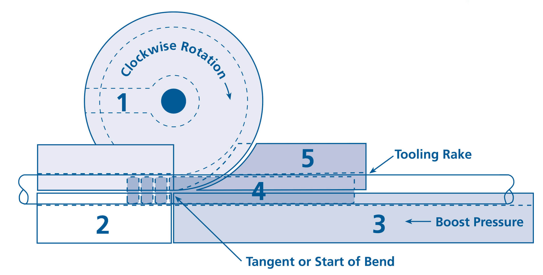
The Design and set up of tooling for rotary draw bending
Typical Example:
- 2.0″ O.D. x .065″ wall on 4″ center line
- Wall factor 30 – 2 x “D” of bend

1. Bend Die
- Hardened tool steel or alloy steel, heat treated and nitrided
- Clamp insert is secured with cap screws and dowel pins
- Drive key must be parallel to clamp insert
- Bore should have a slip fit over centering ring or spindle
Note: Bend dies may have special tube grooves with captive lip or Empty Bending
2. Clamp Die
- Hardened tool steel or alloy steel, heat treated and nitrided
- Preferable length is 3 X tube O.D.
- Tube groove is grit blasted or may be serrated if less than preferred length
- With tube held in bend die, advance clamp die and adjust for vertical alignment
- Adjust for parallel contact with entire length of clamp
- Adjust for pressure
3. Pressure Die
- Alloy steel and nitrided
- Tube groove must be parallel to back of die
- If follower type pressure die is used, length equals 180 degrees + 2 O.D.
- If a boosted system is used, groove should be grit blasted
- With tube clamped to bend die, advance pressure die and adjust for vertical alignment
- Start with minimal pressure and increase as required in small increments
4. Mandrel
- Type of mandrel and number of balls indicated by Tooling Selection Guide
- Aluminum/Bronze, chrome, or Kro-Lon mandrels for ferrous tubing. Only chrome mandrels for non-ferrous
- Gain best results with most mandrels when shank projects a small amount past tangent (bend and try)
- Lube I.D. of each tube
5. Wiper Die
- The Tooling Selection Guide indicates when a wiper may be required
- Push tube over properly located mandrel and bring clamp and pressure dies up to bending position
- Slide wiper along tube as far as possible into bend die then secure to holder
- Unclamp pressure and clamp dies, tip of wiper should be “very close” to tangent
- Adjust for rake and vertical alignment
- Lube each tube and the wiper


