Special Rotary Draw Tooling Solutions
There are distinct differences from what would be considered sets of bender tooling and a tooling system. Simply defined a set of tools typically refers to the (generally five piece) family of dies to bend a tube for a given outside diameter and wall thickness, to a single specified centerline radius. A fabricating company may have dozens of tooling sets each specific to the job it is designed for, and the machine designated to perform the job. In the case of a bending job shop they may have hundreds of die sets.
More often than not in this scenario they have been added over time each for a certain application to meet their customer’s requirements. Many times there is little planning or time permitting for tooling to be supplied as compatible with the dies that are already in house for a given bender mount design, let alone for the dies to be interchangeable over various bending machine mounting standards.
Needless to say that over time this results in dies that are frequently grabbed in haste and used for whatever part needs to be bent and out the door yesterday. Further to this, the mind set develops to modify dies on the fly to suit a purpose they were not originally intended for, becomes common practice. It is an understandable situation happening far too often even in the most organized shop with conscientious well intended personnel.
Bottom line, if the product does not get out the door, on time and to meet the customer’s criteria the company fails to deliver, and in this case you do whatever it takes…. Many times when a company goes through the sustained growth that drives capital expenditure in the form of new bending equipment, new opportunities open for tooling considerations as well. The cost associated with new bending equipment typically dictates a major process of budget setting and multilevel approval followed by significant research into options involving everything from performance and support to service and payback. These factors are all given close scrutiny in the due diligence required to make the decision of investment as informed as possible. In many cases the decision for new equipment is driven by acquisition of new work and in these instances new bender tooling is part of this process.
While this generally means an additional big ticket item to the bottom line, it further makes it imperative that you cover all the bases with regard to what options are available. This situation is an excellent opportunity to consider bringing in a tooling system that can be built on later as well as meeting the immediate project needs. A given bending company more than likely over the years has developed a tooling strategy that they find works for their needs. This can be true whether they make the tooling in house, buy the dies as needed from a given tooling supplier or regularly go out for quote from multiple tooling sources as new projects require.
While each of these directions taken has pros and cons there are many important aspects to consider in this decision. For the most part in house made tooling is advantageous in that the schedule of the tooling design and manufacture is controlled. Most companies that go this route use this fact as the primary reason for the decision and unfortunately the design or quality of the tooling can suffer in the process. The company in question is generally speaking in the fabrication business not necessarily in the tool and die business.
Over the years I have worked with many large companies that have spent an incredible amount of time, money and manpower to develop what they consider to be proprietary die designs specifically to address in house die compatibility issues. While some of these designs were fairly straightforward, others have been so overdesigned for versatility that they are unwieldy, fragile and problematic especially in high production situations.
What was started as an integration strategy to stay in control of the processes can easily become a nightmare. The reality is that when problems develop, parts fail to ship or the quality of them regularly fails to meet the needs, even a qualified and capable outside source has its hands tied to come in and offer more than a quick band aid on the fly.
There is also a more insidious aspect that can develop with this inside integration thinking. Many times the company in question can get so caught up in how proprietary and wonderful the design may be (time, money, manpower…remember), that they concentrate so much about keeping their cards to vest that they fail to look to outside sources and notice new technology that could and should be integrated into their processes. Some of the companies I have seen get to this point over the years, are no longer in existence.
Having the die work done outside by a company specializing in the design and manufacture of the tooling to suit the specific machine and the application, ensures that the investment is well placed. While it is always important that tooling cost be considered it should not necessarily be the final determining factor.
The most imperative consideration to tooling begins with understanding the bending process, and the various design options of the tooling in concert with the application needing to be fabricated. Many times these design options will fluctuate the cost radically, whether or not those options are justified or even need to be considered can save or cost you in the long run. As ultimately you may invest as much into the tooling on the project as the equipment, you must develop and maintain a mindset of understanding all of the processes involved. Partnering with a supplier to work with you from the initial application analysis, through installation, set up training and on-site support is a major leg up.
A common problem encountered is that an existing library of tooling is already on hand and a decision will need to be made as to building on the existing die work or to depart from it completely with a new design. The selection of the new machine will have a major impact on this decision, but the first consideration should by all rights be the application itself. If the new project that is to be manufactured is completely different than the current product being made, the decision is an easy and obvious one (new product, new machine, new tooling). Many times however in situations where the new product is similar or even in cases where the new acquisition is to increase the productivity of the same part, this decision still bears more thought than you might think. It should be noted that most bending machine manufacturers have a specific mounting pattern that drives the die design also.
While some of them may be receptive to building a new piece of equipment with a different than their standard mount pattern (to for instance accommodate your current die library), others may not. This fact should not be a deciding factor on selection of the machine manufacturer per se, any more that the decision of die design be based on the bender itself. Once again the first consideration to select the process, the equipment and the tooling design, is the subject application.
Potential tooling incompatibility from the existing dies to additional ones needed for the new project can be more than exasperating, it can cripple the project before it gets off the ground. Though there are several different methods of tube bending that are used commonly, we will be discussing specifically tooling design using the rotary draw (mandrel) bending method.
Rotary draw bending is by nature more involved and complicated but subsequently the most versatile. It is the only method that is suitable to produce high quality wrinkle free bends in tight radius thin wall tubes. It is by far the most used for any application where support is needed to control the stretching and compression of material and simultaneously prevent the tube from collapsing.
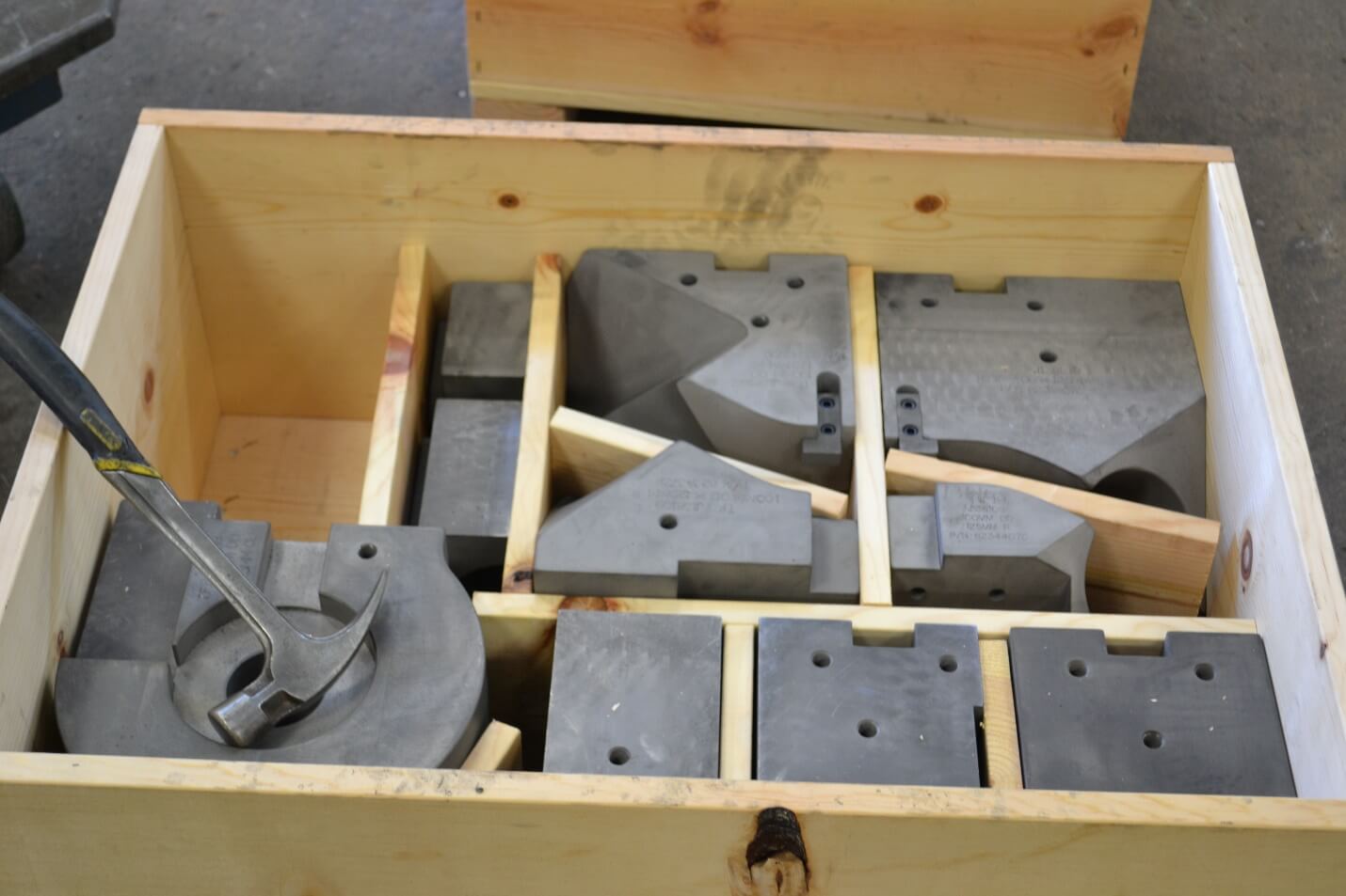
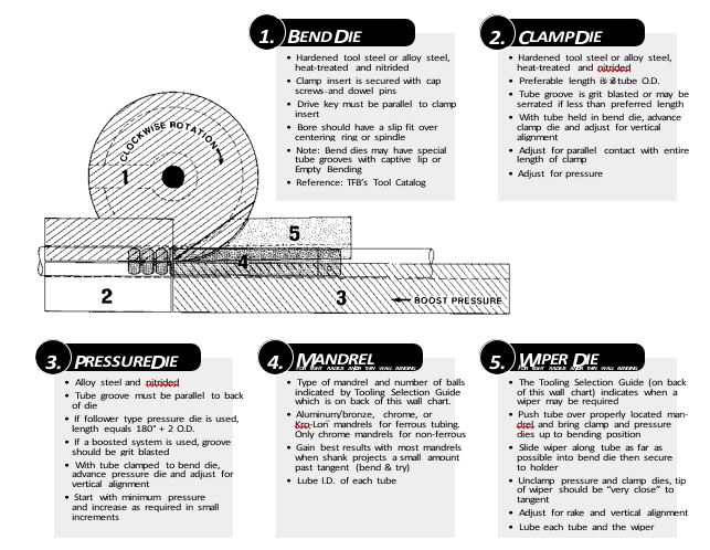
Typical Rotary Draw Bending Set
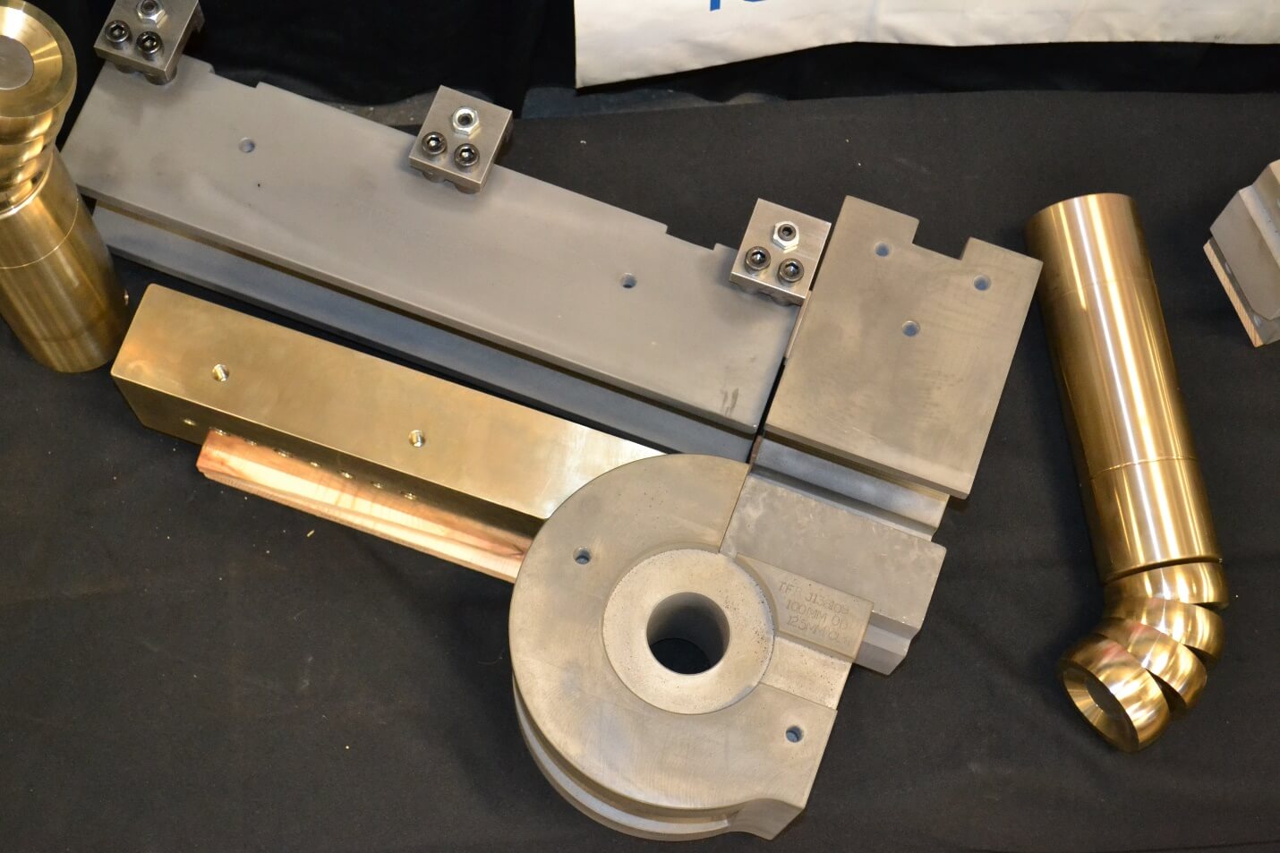
The set consists of:
- The Bend Die…Rotates with the tube forming it to the correct radius.
- The Clamp Die…Grips the tube against the bend die to prevent slipping.
- The Pressure Die…Moves forward with the tube forcing it to conform to the radius of the bend die.
- The Mandrel…Internal to the tube supports the tube at tangent prevents collapse of the tube.
- The Wiper Die…Rides between the tube and the bend die controls the compression side on the bend.
In the process of bending the tube we must control its natural reaction to the process of inner wall compression and outer wall thin out. In a very simplistic explanation the mandrel being inside the tube supports it from collapsing in the bend process while the wiper die prevents the inner wall compression from bunching up and forming wrinkles. In any real world scenario however it is far from that easy.
The first step in the process is t0 ascertain the tooling requirement for the subject application. Before this however determining the basic feasibility of the bends required together with the tube material. Simply put, will the material be able to form at the centerline radius needed based on its elasticity or elongation percentage. Over the years what were once solid limitations as to how tight a certain material could effectively be formed, with the advent of today’s cutting edge equipment and tooling, these rules have grown more generous.
Regardless of this fact the limitations are real and failure to research this aspect of the project at the onset of it is a drastic mistake. As we consider the natural reaction of the tube to the bending process is outer wall thin out and inner wall compression, the tooling must provide the support to the tube to control this. This fact means that the tooling in the case of the mandrel and the wiper die are in a fixed position while the tube is drawn across and over them. This in turn crates drag to the tube compounding the prevalence of outer wall thin out.
In the case of materials with low elongation, the yield point is reached and the tube fractures. The balance point then becomes how much support to offer the tube so as not to go so far as to induce enough drag to fracture the tube. Even with material types with low elongation there are strategies that can be effectively employed to achieve success. The bender selected for the project will need to have all the effective options possible for this. Some of these bender options would include, though not limited to: -Incremental pressure die assist, both in speed and pressure -Anticipated mandrel extraction -Carriage/ collet boost -Automatic mandrel/ wiper die lubrication -Overhead tie bar system from multi points to the bend die spindle and the wiper die bracket All of these options work together with the proper tooling to control the tube.
The obvious goal is to effectively form the tube without fracturing and with the least deformation possible. The discussion of these bender options and their implementation fall outside of the scope of this paper, but suffice it to say are an integral part in the success of any bending project. Let us assume then that the homework has been done and the machine selected for the project is equipped as outlined and the best platform possible to get the job done. We then move to the process of dialing in the tooling itself based on production of the application at hand.
To begin it is best to gage the severity of the application. This will determine whether a wiper die will be needed and will further allow the decision of how many balls will be required on the mandrel to support the tube.
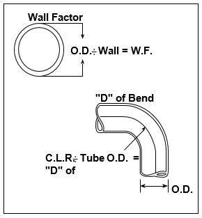
Again, we must provide the amount of support needed without crossing the fine line of too much drag induced in the process. We will then calculate the Wall Factor of the tube. O.D. divided by tube wall thickness equals….Wall Factor. (the higher the wall factor the more severe the subject bend is). This must then be further considered with the D of Bend. The bend centerline radius divided by the tube O.D. equals…The D of Bend. (the lower the d of bend the more severe the subject bend is). Once again these aspects must be then weighed with the tube material elongation percentage as well.
The lower the elongation percentage the less support/ drag the tube will withstand, the result of which is tube fracture. The benefit of providing an interchangeable tooling system is immediate to the project at hand but also provides a game changing platform to build on as needs change. The implementation of tooling that can readily interchange pieces of a die set, be repositioned easily in a stack of die sets to accommodate change overs is an incredible time saver. While in some cases it will mean more individual components the setup and die change over time reduction alone is more than worth it.
There are other further benefits as well. Let’s draw a scenario for the subject project at hand. Our goal will be to produce perhaps forty different part configurations in three different tube sizes. Let’s further assume that each of the different tube sizes will have parts required that have for example three different centerline radius bends. While not all of the bent parts in the project have more than one bend in them, in our project we will be bending perhaps 70% of the parts with three or more bends in each. It is entirely possible that some of the subject parts may have bends of different radius dimensions in the same piece of material. This will by necessity be stacking multiple sets of dies on the bender.
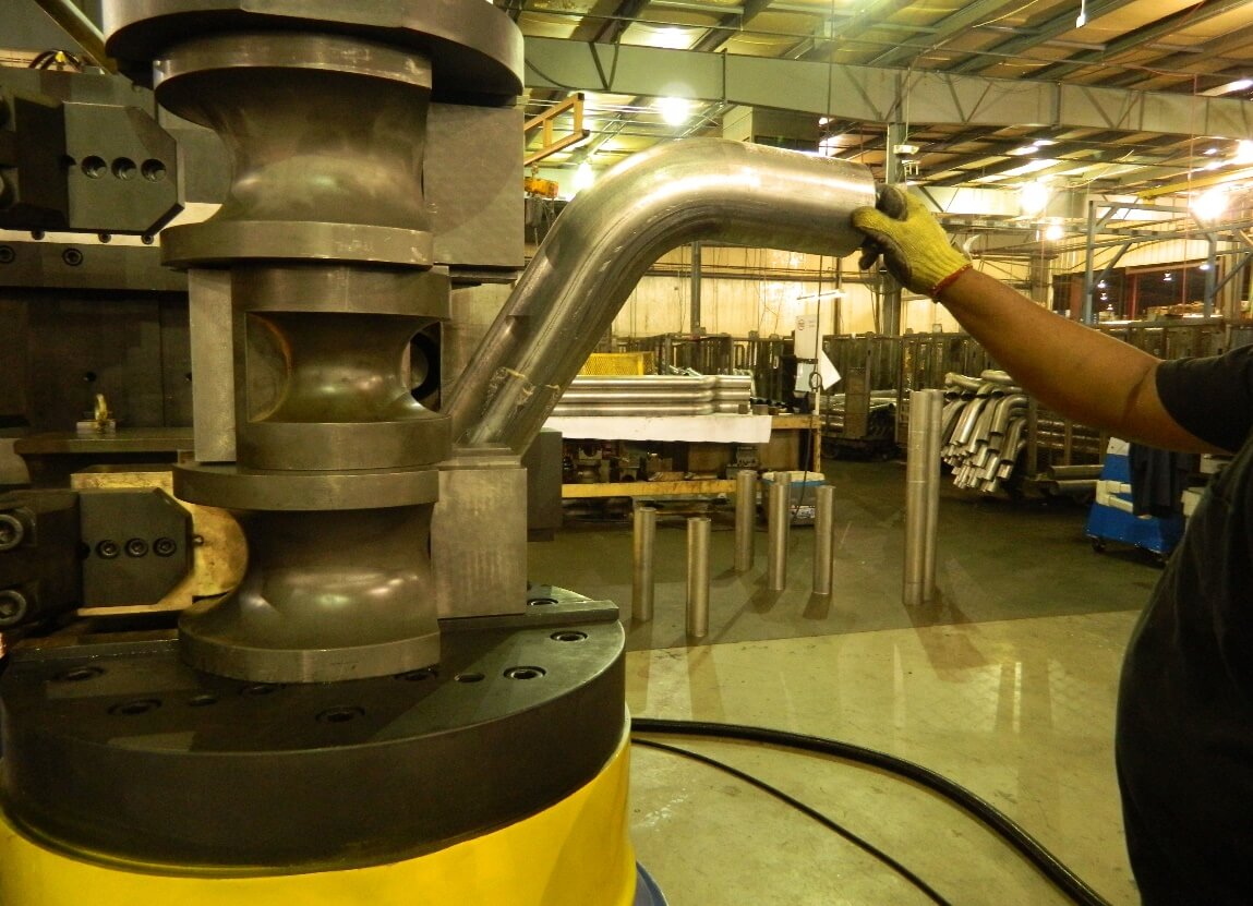
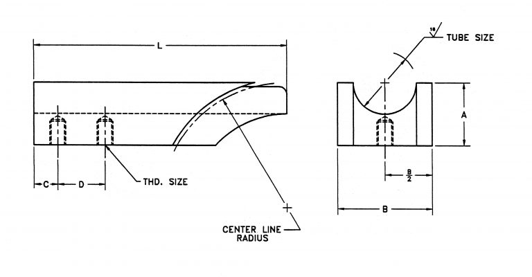
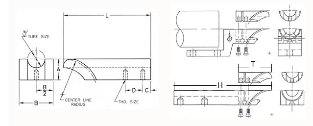
The CNC machine will then position the tube automatically to the correct die set in the stack for each bend moving it forward and rotating it between the bends based on the XYZ coordinate data programed in for each part. There will be certain parts in the project simple enough to require a straight forward single die set, and in those cases the machine will go through the same motions as noted but with no need to transfer up to a different level in the stack. Here is a visual example of a tube that will represent parts typical to our hypothetical project.
It stands to reason that if we look simply at one in this scenario that we will require a different bend die for each bend radius needed. Each of these bend dies might need multiple gripping lengths dependent upon the part configuration needed. The system we will build will then have the ability for each bend insert to interchange into each bend die in a common . Every bend die insert will have the same bolt hole pattern allowing for a minimal number of hand tools and time to change to a different length or surface finish. All the bend dies will be exactly the same height with the machine mount provided on both the top and bottom so that they will all sit on the machine the same (or in any position in the die stack) regardless of or of centerline radius.
It will be possible to preset certain die stacks if needed to load on the machine as one unit to further facilitate quick die changeover for part changes in production. All the mandrels will be made where possible with the same length of shank and thread size. And all wiper dies with a uniform mounting pattern. Die sets or stacks could be pre-assembled based on tube part number prior to the machine operators shift based on the daily production requirement for the job. The benefit for the long term building on this foundation is substantial as well.
In an all too familiar scenario of part dimensional changes in production and additional parts thrown into the mix, the interchangeability of the die system is obvious. Now assume that your customer (or a new customer entirely needing an emergency prototype etc.) throws in a part of the same but a different radius. The additional dies needed by your tool supplier will simply (and quickly) be a new bend die body and a wiper die rather than an entire new set. The ability to have this versatility work for you is an immediate return on investment. The long term benefit can be the start of an entire new direction of thinking for production problems far too familiar to many.
The Building Blocks of the System
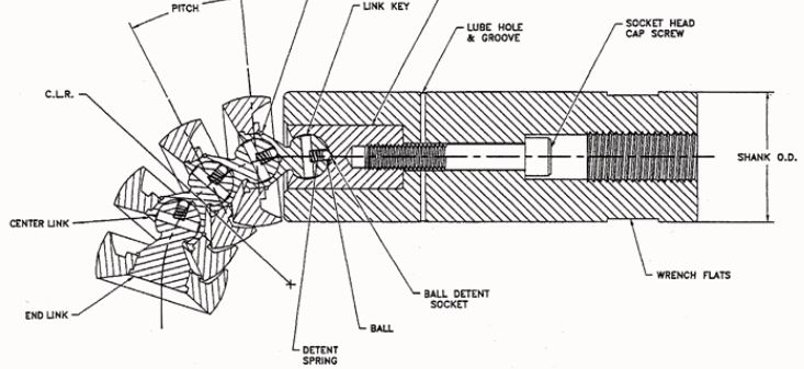
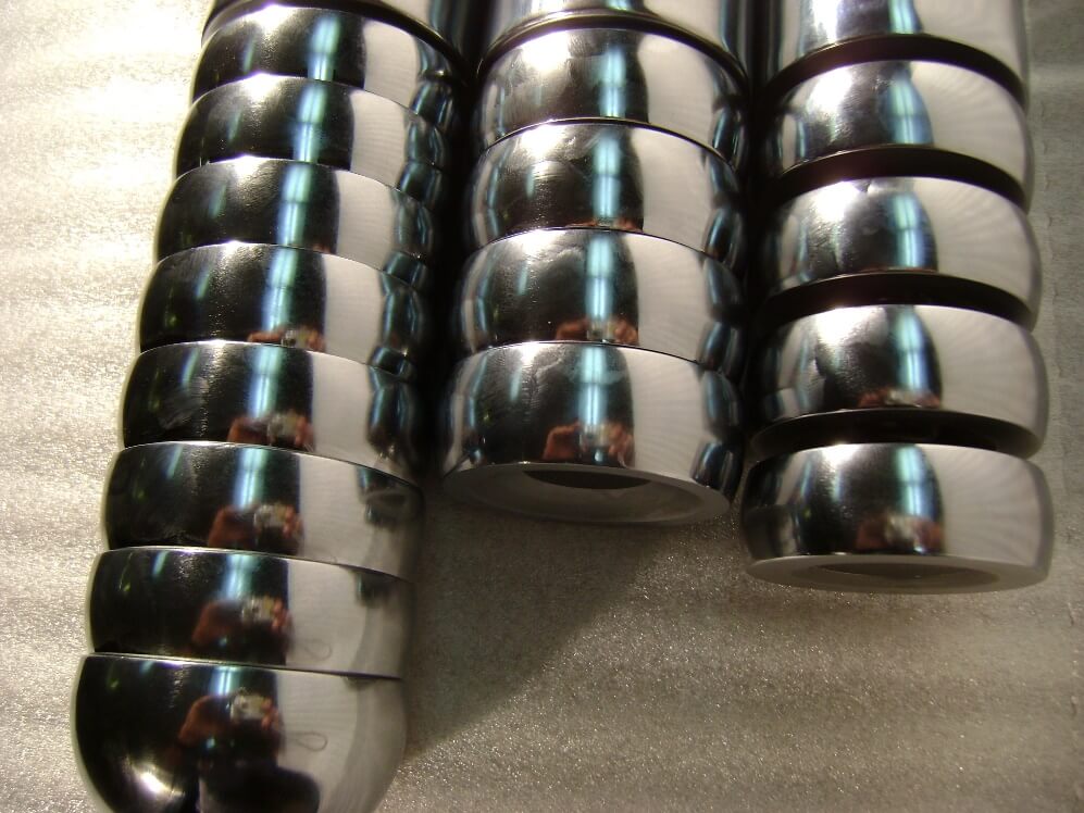
The Bend Die
The bend die is the backbone of the tooling system we will develop and build upon. For obvious reasons the type 6 die shown on the previous page is in most cases the best to consider for the versatility of the removable grip design. This is also a beneficial design for tooling strength as the grip insert bolted in is fully supported by the body of the bend die itself, rather than in the design of the type 1 die (inserted spool) where the grip is left unsupported for a portion of its length.
Either of these bend dies offer greater versatility in that the grip area can be exchanged with one of a different length or even a different surface finish. The grip can be made with directional serrations to aggressively grip the tube even on the shortest gripping length. These serrations can be made with different peak spacing and height to make them finer and thus minimize the amount of surface marking to the tube. An alternative tube groove finish that can provide even the shortest grip with the ability to firmly hold the tube is a tapered knurl finish.
While this has the impression and appearance somewhat to a typical knurling process. The ‘knurl” is machined into the surface of the die. While this will still mark the tube surface in the bending process, the marks are less noticeable and it is possible through a secondary operation to reduce them to even less of an issue. As we discussed, the bends get more severe as the tube OD increases, the bend radius decreases and the wall thickness of the tube gets thinner, all of these aspects draw on the decision of the bend die design. The grip length and surface finish being simply one of them.
The break point on when to change from a relatively simple design of the type 1 to the type 6 is based on the amount of grip insert that will be unsupported. As the radius of the type 1 die gets tighter the amount of material that will fully support the grip area is reduced. If that reduction means more than a third of the length of the grip insert has no backing the grip can in extreme situations weaken, deflect or even break.
Type One Bend Die
More often than not we would move to a type 6 design and be done with it. As we are building a system to ensure optimal compatibility we are going a slightly different route. It has been found that using the attributes of both these dies in a hybrid design can bring about the most versatile and strongest platform This will be the first design point we will build on. First however we need to get some other basics considered. There are several schools of thought regarding Interlocking dies that should be factored in as well at this point.
Reverse Interlocking
Non Interlocking
The most obvious advantage of interlocking tooling is that it self-aligns to a degree but most importantly the alignment of the tooling to itself (once the hangers are adjusted and locked down), is consistent set up to set up. These hangers for the clamp and pressure dies respectively once set should not be removed from the tooling, ensuring that every time they are put into the tooling set the alignment is there.
This makes any adjustment or tuning of the tool set changing from one to the next minimal if needed at all. The interlock “shoulders” if you will, are also very beneficial to the die rigidity on the machine. This is due to the fact that the interlock will make the overall diameter of the bend die larger. This can be very important on setups of dies where we will be stacking as many as four or five high on the machine.
Whether or not to utilize interlocking in your tool system “matrix” does to a point depend on the company’s machine operator preference. It was typical especially in old school bending houses that as the interlocking die design can obscure the machine operators line of sight to the point of tangent where the bend is taking place and the relation of one tool to another in the setup, that some preferred non interlocked dies.
It should be noted that in most of these cases that these were very low volume high degree of difficulty applications where absolutely every single bend had to count and high production non-existent. Incorporating interlock design in today’s fast paced production environment where quick accurate tool changes must go without a problem and minimize downtime is a must to consider.
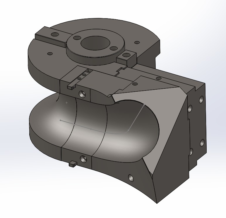
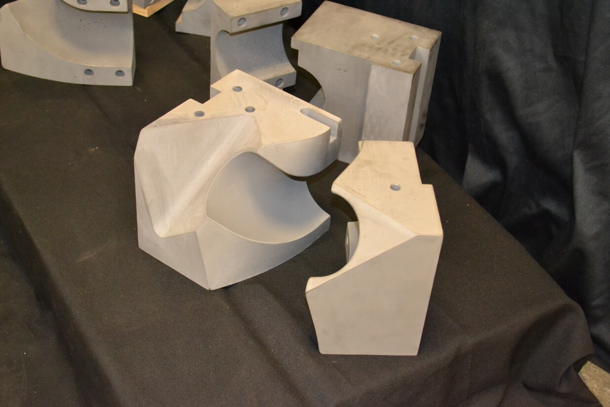
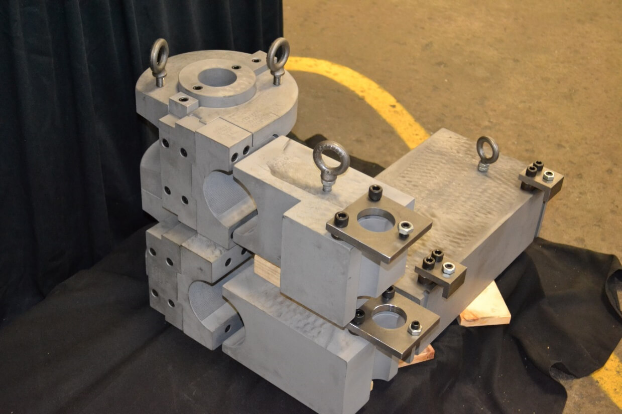
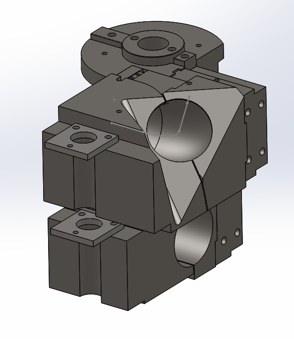
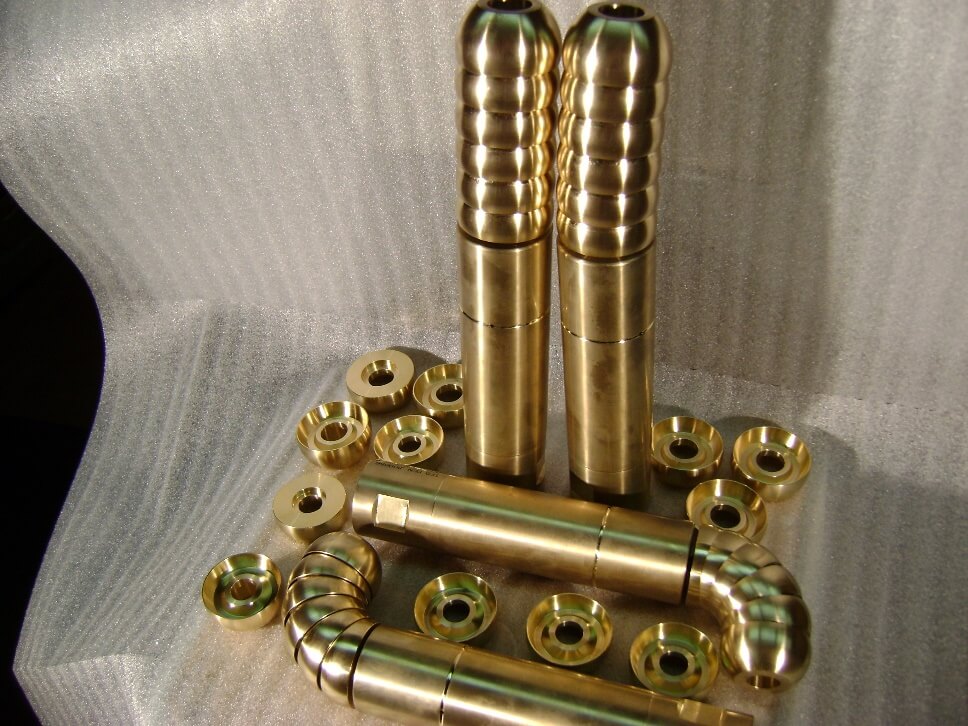
Gusseted Spool Bend Die
The bend die design we will build on for the system will be a gusted spool configuration. This is a three-piece design having the advantage of the removable grip, and the grip insert removable all the way to the tangent point of the body of the bend die. The advantage being that the inserts can be readily changed between different bend dies of the same tube OD.
The third piece in the bend die assembly is the gusset or insert support block. This bolts to the main bend die body and the grip insert both to add a much stronger assembled unit. Further it fully supports the grip insert on the bend die body. Just like bend die insert interchangeability, the gusset blocks for the most part are designed to do the same. However, the gusset blocks design can vary as the need for this support and strength changes. The most obvious change would be that the length can be made equal to the grip insert.
As the insert is swapped for a longer one, so is the gusset block. In extremely tight radius dies it can be an effective increase in strength for the gusset block to have an integrated male key that locates into the bender’s drive keyway (note the bolted on drive keys on the bend die body shown above). The gusset block then ties into the bender and any bend die stacked on top of it more securely. In very tricky die stacks especially with compound inserts that can be long, large and heavy, the gusset block can be designed to bolt to multiple bend die bodies and their respective inserts.
It should also be noted that the advent of this design can in many cases preclude the need for many “special” bend dies to accommodate certain problem parts. As you have the ability to reconfigure the bend die matrix to suit the part configuration rather than a complete bend die being required in those special cases. The benefit of the three-piece bend die design more than outweighs the additional components required
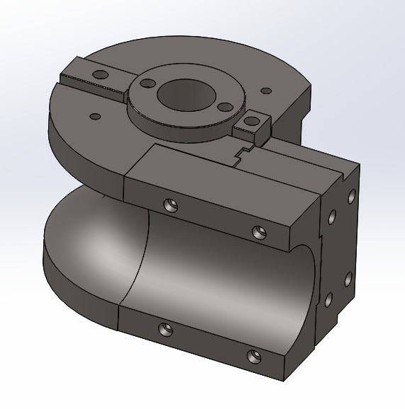
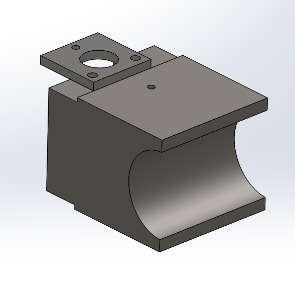
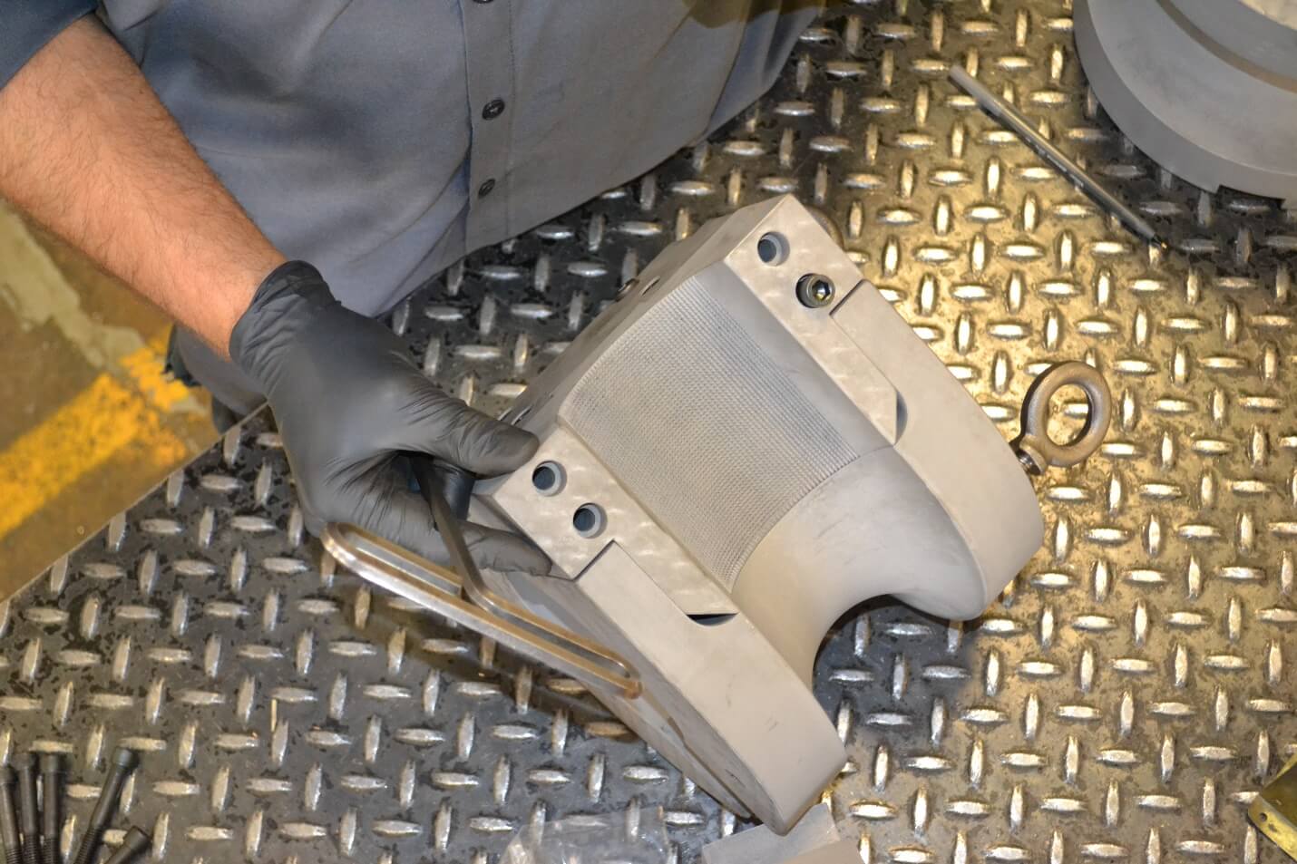
Clamp Dies
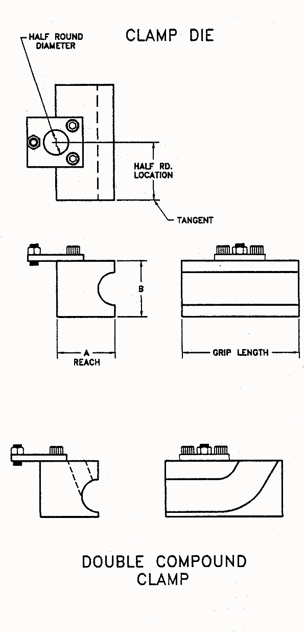
As we discussed earlier making the clamp die finish more aggressive (serrated, knurled etc.) can greatly reduce the die length needed to effectively hold the tube and prevent slippage during the bend. While this will work in most cases to enable parts with minimal straight material between the bends it will as mentioned mark the surface of the tube.
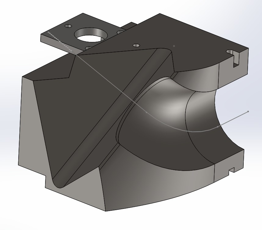
In the case where this marking is not permitted or where there is little to no straight tube between bends it becomes necessary to actually grip on one bend to produce the next one in a multiple bend part. This is known a compound clamping. The rotational orientation (plane of bend rotation) of the first bend to the next successive bend can be problematic.
As most rotary draw bending machines operate either clockwise (right hand bender) or counterclockwise (left hand bender), it is obvious that you will inevitably get to a point where the previous bend to be gripped on will be in an unfortunate orientation to produce the next adjacent one. In many cases the action of producing bend number two etc., might cause the previous ones to crash into the machine the tool holders or the tools themselves.
Often resequencing the part is necessary flipping it over and starting from the opposite end. One of the great advantages of stacking multiple bend dies is that often a situation where the previous bend would rotate down and crash the machine (or prevent gripping for bend number two entirely), the set of dies that produces bend two can be moved up in the stack to alleviate the collision.
In situations where the interference caused by the configuration of the tube to be bent and limitations of the machine itself is too severe to resolve any other way, a bender of the opposite rotation (CW/CCW) might be needed. Another alternative would be to bend this particular part in multiple pieces and weld it together later, more often than not however, if this part was original quoted as being formed in one piece to your customer, it is unlikely this option will be open.
The other generally last alternative would be to consider a machine that is both left and right capable adding great cost to the project to say the very least. Obviously the potential for bent parts that will be problems down the road need to be identified absolutely as early in the entire process of research before the job is quoted.
These are the classic mistakes that kill the profit in the final production of the job Once again, the selection of process equipment and the tooling is driven by the application. If your lack of planning on the project means the application is not the driving factor for this, the mistake will cost you down the road.
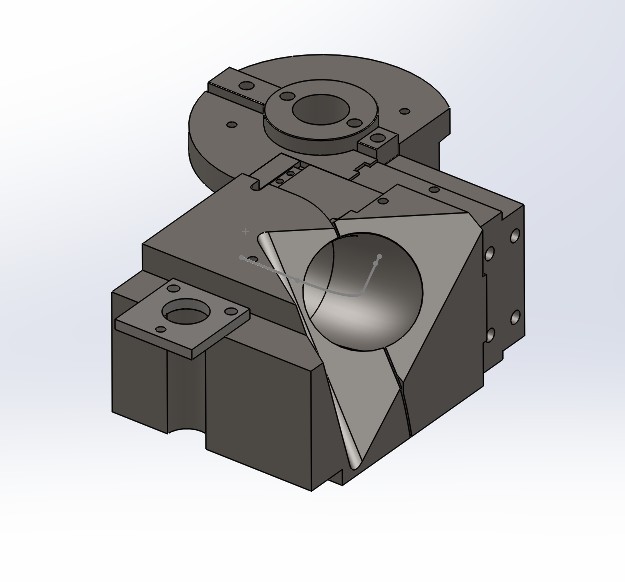
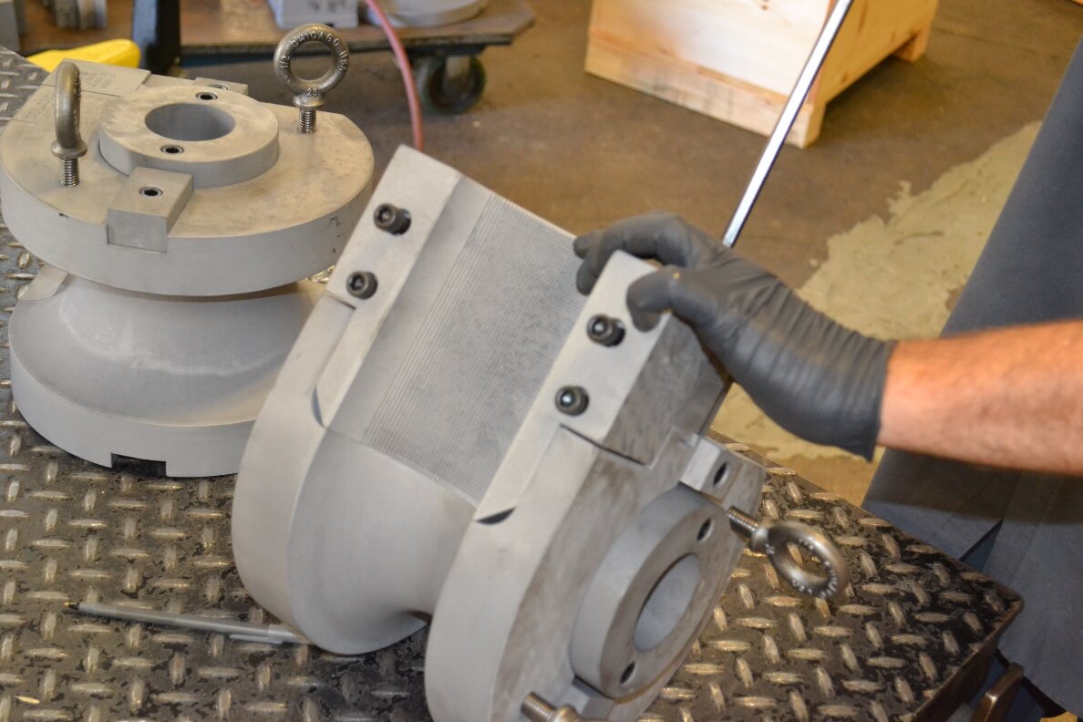
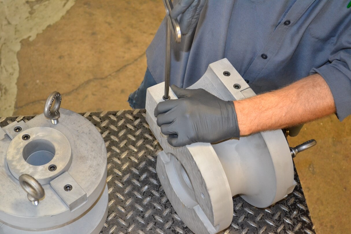
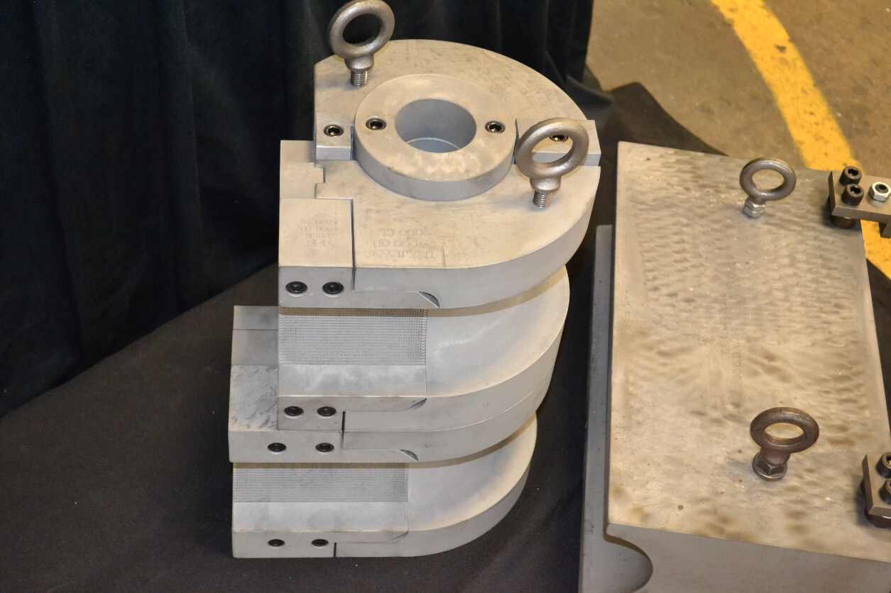
Full tool Stack
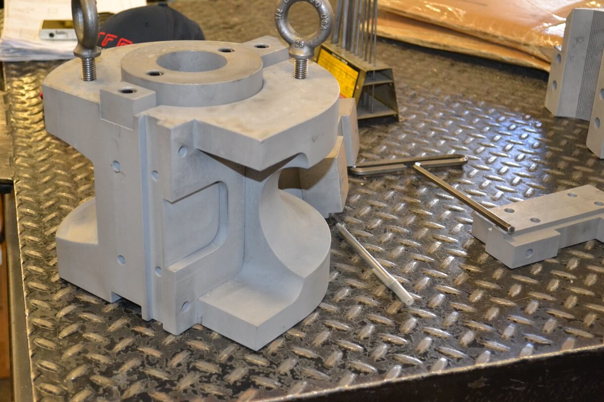
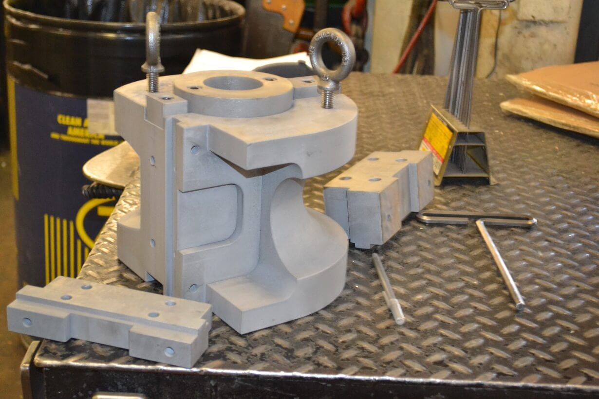
Bend Die Showing Insert Pocket
Gusset Block
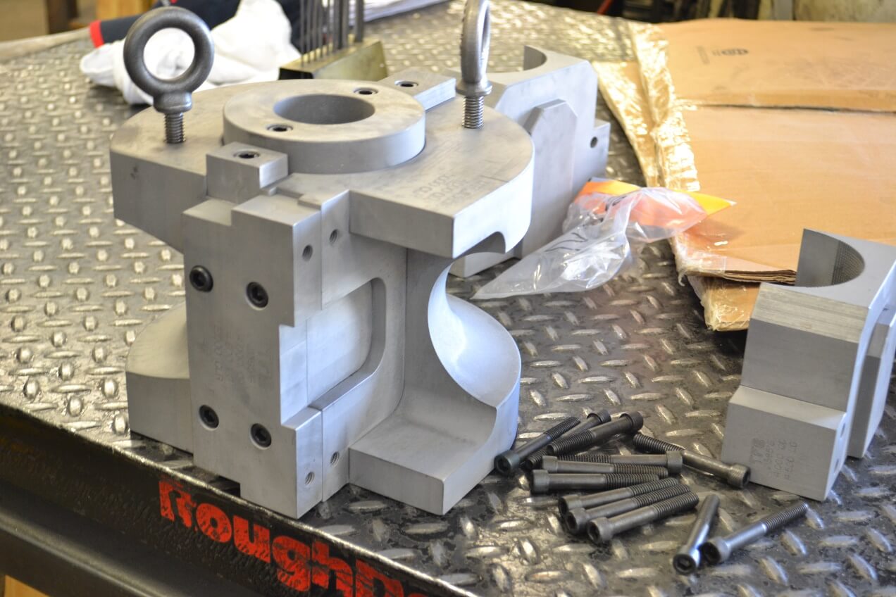
Gusset Block Assembled
Clamps and Lower Pressure Die Added
Moving on to the rest of the individual components within the die sets, we will discuss in brief the remaining pieces. These were mentioned earlier and of all the rest of parts of the set are to an extent “consumables” as again they are in a fixed position relative to the tube being formed. Because they are both in a fixed position they must be lubricated in the bend process to avoid galling and extend the life of the dies.
Mandrels
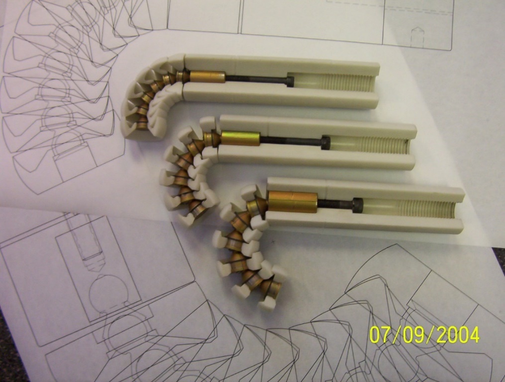
Standard pitch h type mandrel parts & Assembly
Ultra-close pitch (top) For 12.0″ Tube and close pitch for 10.0 tube
Cutaway mandrels shown (from bottom to top) standard pitch, close pitch and ultra close pitch. Ball material is delrin
With regard to mandrel design the first rule is keep it as strong and simple as possible and still meet the needs of the application. If a simple plug or formed tip mandrel will suffice and give you the bend quality you need, common sense should dictate not to go into a ball mandrel scenario. The mandrel is internal to the tube in a fixed position relative to the tooling set up. The tube will be drawn over it in the bend process. The correct and first trial point the mandrel should be placed, is to have the leading edge of the main body of the mandrel projected slightly past the tangent point of the bend die. The goal in the case of ball mandrels is to have the strongest part of the mandrel (the body or shank) do the bulk of the work in supporting the tube. Ball mandrels can be manufactured from various materials each having advantages for tubes of different material types.
Choosing the correct balance of strength and support
It is imperative when selecting the correct mandrel for the subject bend, that we go back to the basic guideline discussed earlier. We start again with the correlation of wall factor and D of bend. Using the chart included later in this paper will help you in determining the correct pitch of the ball mandrel and how many balls the assembly will require. First we will discuss some other basics.
Once again the strongest solution appropriate is the best route to take, but it will certainly have its limitations. The inherent reaction of the tube in the bend process is inner wall compression and outer wall thin out. Our goal then is to control the material and balance this stretching and compression. Obviously left to its own flow in the bend process, any given tube will flatten and collapse.
The mandrels primary function is to prevent this. A heavier wall tube will require less support to accomplish this while a thinner wall tube will require more. The more support you add the more drag you induce in the process. If the amount of this support pushes this drag too far, the wall thinning will exceed the yield point of the tube and it will fracture. This fact makes the balance point of correct support vs minimal drag requirement, a very tricky one. This is further made worse as the wall factor gets higher, the D of bend tighter and we then weigh in the tubing material type.
The tubing material type (and its subsequent yield, tensile and elongation percentage), must be considered at the onset of mandrel selection. It is a basic principle in any metal fabricating process that friction induces drag, heat and subsequently galling. Tube bending is no different. As the mandrel is at a fixed point and the tube being drawn across it, friction is the natural result.
That said selecting the correct mandrel material type and /or the correct surface finish (polished, plated or otherwise surface treated), is the first step. As a general rule a hardened steel mandrel with an application of industrial hard chrome (Hexavelent Chrome, not its decorative cousin Triavalent Chrome), is a universal material for bending most materials.
The type of raw steel will vary but typically could be heat treated 06 tool steel for small diameter mandrels or carburized 8620 steel is also common for larger ones. Full heat treated tool steel such as S-7 as an example is also used, but is more commonly incorporated in mandrels for bending non-round tubing. The bottom line here is due to the hardness of the chrome, the base steel supporting it must be an appropriate and strong platform to prevent the chrome reacting like an eggshell and cracking with the load we will induce in the bend process. Simply put Chrome over steel will especially be a good choice for bending any non-ferrous material. Aluminum, brass, copper etc. will tend to gall less on the polished chrome surface.
Chrome is also widely used on most steel applications including aluminized, galvanized and zinc coated. It is also a good choice for non-coated low carbon mild steel as well as high carbon high tensile steel tubing. The tube materials that do not react favorably to the chrome would include nickel alloys, stainless steel, chrome molly steel, inconel, monel and titanium. There are many more coatings to consider over a hardened steel substrate. These would generally be used for the same subject tube materials noted. Some of the most common of these would be Titanium Nitride (TIN) and Titanium Carbo Nitride (TicTin).
The substrate material for these more exotic vapor applied surface coatings is more often than not a full heat treated ground and polished D-2 tool steel. It should be noted that the base material, its preparation and the fact that these coatings must be done by a company specializing in the process, bring additional cost and lead time into the equation.
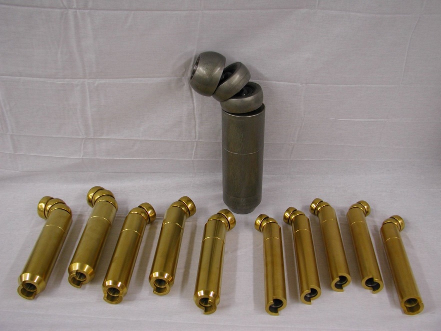
Tin coated mandrels (foreground) krolon plated steel in the back
Ampco ultra-close pitch mandrels and ball segments
By far the most common material used for mandrels has historically been bronze. Generally speaking this will be aluminum bronze under the trade name Ampco. Ampco material is supplied in many different grades Ampco -18 being the most common. Harder grades being considered in many cases to avoid the short service life of aluminum bronze material inherent in the load and friction involved.
While the harder grades such as ampco-21 have advantages in that it will hold up longer, there is an important trade off. As the hardness of the alloy gets higher its grain structure increases as well. All of us learn quickly in a shop environment that harder materials wear less but are more brittle. The larger grain and harder grade can be problematic for mandrel balls in particular as frequently the necessary design and thin section width will cause them to break, though using it on the shank of a mandrel will increase its life substantially.
Ampco has been the go to mandrel material for many years, most especially for stainless steel, Inconel and titanium. It has also been a very prevalent issue and for as long, that using bronze for almost everything else as well has become a common practice. The bronze is more forgiving in that it will produce passable results even if the lubrication used is inadequate or pre-cleaning the tubes is omitted.
The mandrels do not live long in this scenario. While this for the most part will work in a job shop environment (and in some cases would prevent necessitating the same size mandrel be on hand in chrome), the cost of replacing them more frequently is not the most cost effective solution. It should be noted that using bronze mandrels to bend softer non-ferrous materials such as aluminum, copper and brass is not the best route either, stick with chrome on these.
If you have an application than requires you to consider bronze for mandrel components make certain that you have explored other alternatives. In a high production situation, the cost of replacement and the need to maintain a supply of parts on hand is something you must consider.
Another mandrel material/ surface finish alternative to consider would be Krolon ™. Krolon is a derivative of the hard chrome process previously discussed. For this process we go back to the hardened steel substrate followed by the application of the hexavalent chrome. In a controlled process the chrome is impregnated with Teflon ™ (a product we are all acquainted with developed by DuPont). In this patented process the surface of the specially prepared chrome is etched and then under heat, the Teflon bonded into the surface. Give or take, the ratio of chrome to Teflon is 65% chrome 35% Teflon. The combination of the hardened steel base with the Krolon can be substituted in most applications that bronze is commonly used and across mild steel to high tensile steel as well. It is particularly effective with Stainless steel including 4000 series aluminized. It can also be a solution for nickel based alloys with the proper lubrication.
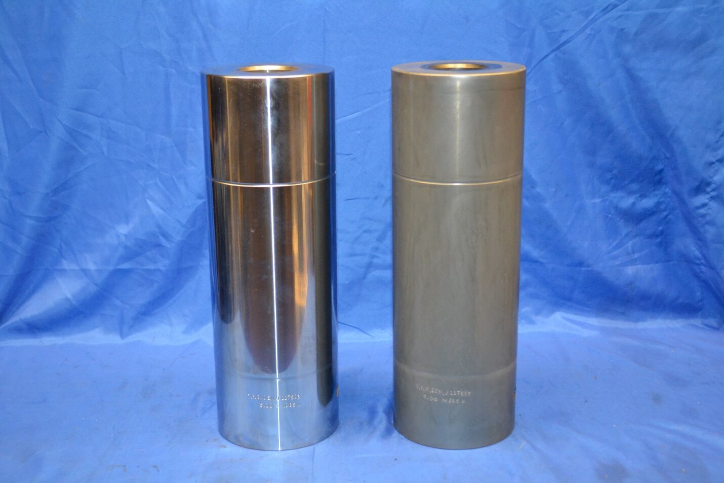
Chrome Mandrel shank (left), krolon mandrel shank (right)
One other type of mandrel material that bears mentioning is plastics. These are primarily used in the aerospace industry and as such are not generally suitable for the rigors of high production work. For the most part they are used for very thin and soft aluminum. The types of high density and high durometer plastics include (though are not limited to) various types of nylitron and delrin. What the life expectancy of ball mandrels is in these materials is hard to gage.
The typical production rates in the thin wall fragile materials in the aerospace industry are radically different than in a high production scenario such as automotive for example. As far as the cost difference is concerned mandrels will run a bit more to be made in these materials over bronze or steel but allowing for the low volume of parts run on them to be amortized into the equation, the cost per bend jumps substantially.
It has been said that in some cases the lubrication that is used on certain plastics and tube materials in simply water. As the methods used in aerospace circles are rarely discussed outside of that arena, I honestly can’t confirm the validity of that statement. That said, on the subject of lubrication, there are many variations to consider. There will be compounds that are best suited to certain materials and possibly the wrong thing to consider on others.
The selection of lubrication based on material type is a multi-faceted one as consideration must be given both to its effectiveness but also in how it is removed from the tube following bending. This lubrication process analysis falls outside the scope of this paper but simply put, all tooling that is fixed in the forming process requires lubrication. This must be the correct type and adequate amount. It is crucial for the proper working of the tooling and to extend its service life.
The surface finish of the product you are forming depends on the integrity of the dies and they and the tube are dependent on a suitable barrier film of lubrication to achieve it. There are no exceptions to this. No material type, plating or coating will preclude the need for lubrication. To omit this is to sacrifice the tooling prematurely and your bent tube quality in the process.
Ball mandrel variations (round tube)
In standard multiplane flexing mandrels, most utilize a common ball and socket design linkage. There is a term that is frequently heard regarding these mandrels, that word is pitch. The pitch of a ball mandrel can be simply defined as the dimension from ball center to ball center. The aspect of mandrel design that determines its pitch is the physical size of the articulated linkage inside it.
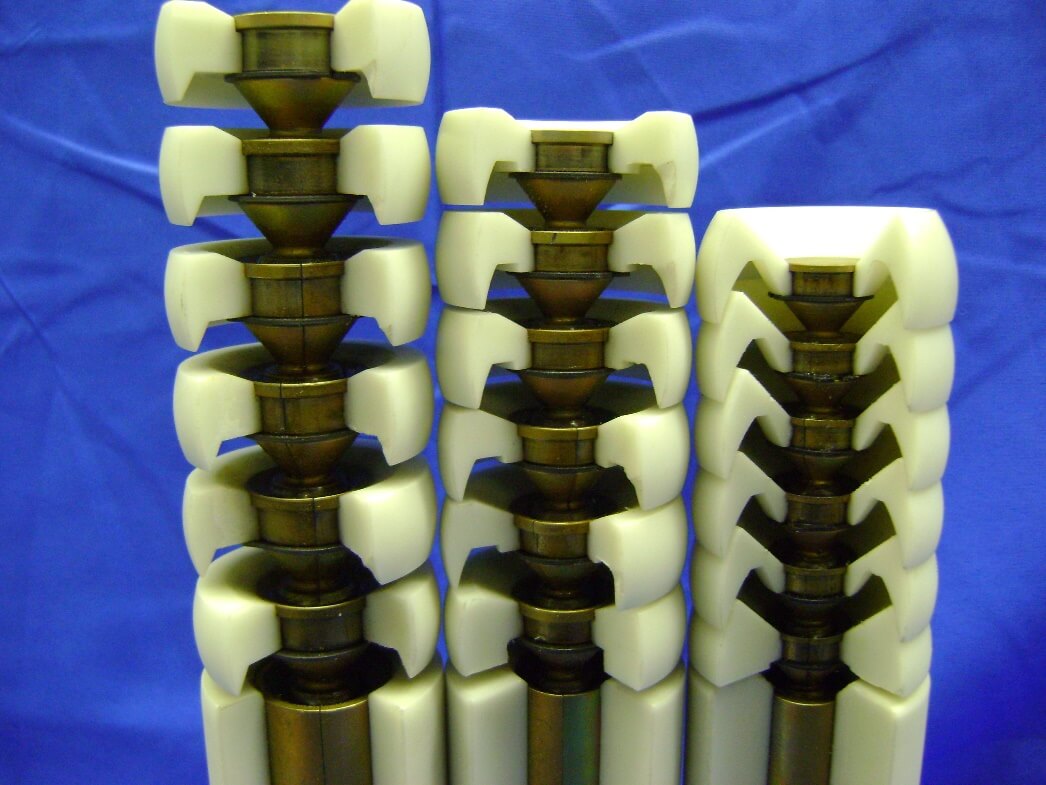
Cutaway shows the changes in mandrel ball cross section and design neccesitated by dropping from standard pitch (left) to ultra-close pitch (right)
Or more specifically, the distance on the link from the center of the male ball on the one end, to the center of the female socket on the other. The pitch of the mandrel will determine how tight (measured as centerline radius) the mandrel will be able to flex in the bend process without the components crashing. Common sense dictates that the larger the link the stronger it is, but the limitation is that it will not flex as tight.
What determines a mandrel to be designated as “close pitch” is that it utilizes the next successive link size smaller than standard. Subsequently, an “ultra-close pitch” mandrel drops two link sizes in its design. As the wall gets thinner on the tube to be bent and the bend radius gets tighter dropping the pitch of the mandrel is the only way the tube can be adequately supported and the flow of material controlled. There are other linkage designs associated with multi ball mandrels though by far the design shown in the photo above is the most uniformly used.
A word here is appropriate regarding the diameter of a given mandrel in comparison to the tube internal diameter. There is a distinct need for the correct clearance between the body or shank of the mandrel to the inside diameter of the tube. Too tight a fit and the internal drag to the tube will be too great and too sloppy a fit to the tube and too much collapse and the inability to control the inner wall compression will be the outcome. While the placement of the mandrel shank relative to the point of tangent can be adjusted (and this is necessary to dial in the optimal position for bend quality) if the overall diameter is too far off this adjustment may not be sufficient or even possible.
The generally accepted standard of the correct amount under the ID is a percentage of the tube wall being bent. This means that the clearance amount is not a fixed dimension, it is a ratio of the tube wall. This is an important distinction. The common amount used is generally 25% of the tube wall to equal the total clearance from the shank of the mandrel to the tube ID. That is the total clearance not the clearance per side. To crunch some hypothetical numbers. A 2.00” OD tube with a wall thickness of .080” wall, will have a clearance from the shank to the tube ID of .020” (or .010” per side). When bending heavy wall pipe, the numbers change a bit and a 30% to 35% clearance factor is not uncommon.
In aerospace work and when dealing with applications having high enough wall factors to dictate a close pitch mandrel, a clearance percentage of 20% is more appropriate. For extremely high wall factors running 160 to 200 WF. A clearance percentage of 15% is customary. An important fact to consider is that in all the above cases the mandrel balls are always made to run .003” to .005” under the diameter the shank is. If the balls are at (or worse greater than) the diameter of the shank. The shank of the mandrel in the bend process is doing virtually nothing and all the resulting load falls to the mandrel linkage. More often than not this results in mandrel link breakage.
Wiper Dies
The wiper die is the last piece of a typical set of tooling. The function of the wiper is to control the inner wall compression of the tube in the bend process. This compression is the natural reaction to the tube and it is inherent to the process regardless of material type wall thickness or any other factor. In the case of a heavy wall tube the compression will in most cased be inconsequential on an aesthetic basis and a wiper will likely not be required. In applications where The tube is thinner, the resulting inner wall compression will result in wrinkling on the inside of the bend. This wrinkling can get so severe that it can and will tear the ball string of the mandrel apart if not controlled. In the tooling set-up the wiper die is positioned against the tube groove of the bend die. The tip of the wiper is located slightly behind the tangent point of the bend die.
The wiper is machined to a very sharp tip in the tube groove area the tip thickness is typically held at .003” to .005” when new. The most cost effective wiper die is the most accurate and correctly machined. Wiper dies that are too thick and inconsistently made will result in a frustrating and time consuming tool changeover every time. The correct set up of a wiper die is such that it is set off parallel to the grip face of the bend die. The tip end of the wiper will be doing the work the back end of the wiper is angled away from the tube being bent slightly Too much angle and you might as well not have one there, and too little angle and the wiper will act as a second clamp to the tube when the pressure die comes in and the bend begins.
Just as discussed with mandrels the wiper die is in a fixed position relative to the tube sliding through it in the bend process and as such the selection of material type and the need for lubrication is just as prevalent. It should be noted however that due to the design of the wiper having the thin machined tip that the die cannot function properly if made from a base metal that is too hard. This will inevitably result in the tip being torn off in the bend process.
Likewise, any sort of plating or coating process that would cause damage or deformation to the tip must be applied to the wiper blank after the tube groove has been machined and before the tip is cut and hand dressed. More often than not the go to material for wiper dies is bronze especially for stainless steel, inconel and titanium. Bronze is also used in applications where scratching to the tube cannot be tolerated. As was mentioned earlier, the trade off with the bronze is the high wear and frequent replacement needed.
Steel wiper dies made from alloy (4230 / 4140) are also used. Typically, they are pre-heat treated prior to the machining process at 28-32 Rc “C”. The tube groove can be hard chrome or Krolon plated prior to the wiper tip being machined. The same reasoning as was outlined in material selection for mandrels is applicable to wiper dies as well. Wiper dies can after the wear that occurs to them be re-cut and be returned with the tip ready to go back into service. This will obviously result in them being out of plant periodically which needs to be planned for.
It should also be noted that each time a wiper die is reworked it is made shorter and the width thinner. The reason the block is returned thinner is that the tube groove in the wiper die will generally need to be re-machined to get the worn out groove contour correct again. Following this the face of the die topped off to get the tube groove depth correct again. Bottom line the wiper die will come back to you a different size than it was. In the case of production high enough that you will need a supply of wipers on hand, the quantity you need will go up. Some will be on the machine, on the shelf, out for repair at any given time. The fact that in the recut process they will by necessity come back with the block sizes varying. This can be quite problematic in the attachment of them to the bracketry on the bender. As they are no longer uniform in size, more time is then spent in getting the proper alignment with the tooling setup. This can result in test tubes needing to be run to dial the bend quality back in. This will not be the scenario you want in a high production environment.
Wiper Die Tips
The design of a round back removable wiper die tip is such that as it wears it can be quickly removed and replaced. The holder for the tip remains bolted to the bracket on the bender. This means that the alignment of the holder remains a constant in the set up. This tip placement consistency is a major improvement to changing over standard square back wipers especially if the wiper block sizes are not uniform from re-cutting.
The tool changeover time to replace worn wipers is now reduced to minutes and with no need generally to run a trial bend before resuming the production part run. For the most part the wiper tips can be used in any situation where a standard square-back wiper would be required, but there are exceptions. The raw material used in the machining process to make the radial back wiper tips starts with a heavy wall (steel or bronze) tube.
The OD is turned the ID is bored, and finally the tips are machined from the outside, one 180 degrees from the other. Two tips face to face in one blank of material. The next step of the process cuts the two apart. This results in the tube groove depth being slightly less than 50% of the tube diameter. While this will be absolutely fine for 90+% of the applications that require a wiper die, in very high wall factor situations they could be problematic.
In most rotary draw bending tooling scenarios the part-line of the dies is on the tube centerline. 50% of the tube is contained on the bend die and grip insert side, while the tube grooves in the clamp and pressure die side are somewhat less. The reason for this is to allow the tube grooves to be able to engage and work the tube in the bend process. Without the resulting gap the dies on one side of the tube will contact the dies on the other side.
This compromises the pressure and control to the tube from the tooling. Having a gap is critical to being able to achieve the high quality bends we strive for. As a general rule if the set up indicates that the gap is gone and the dies touching in the bend process, there is enough die wear that you have a problem that needs to be corrected soon. If this goes un-checked it can actually cause the mount surfaces on the tooling holders on the bender to become miss-aligned.
This can really start a chain reaction that easy recovery is not the likely outcome. In the setup of dies on the bender the pressure die is on one side of the tube while the wiper opposes it. If it is a radial wiper tip and the tube groove depth less than 50% of the tube groove diameter in depth, the resulting gap between the wiper tip and pressure die is probably double what it should be. Again, this for the majority of applications is not a concern.
If, however you are running extremely thin wall large diameter tubes to a 1XD bend the gap may be great enough for the tube to want to creep into. The result will be a very noticeable mark or bulge ion the top and bottom of the finished bend. In high production bending the necessity of fast changeovers and consistency of die alignment is critical. The wiper tip is an integral part of that system Shown on the diagram on the previous page is a special wiper tip holder machined with a dog leg to allow for the bender’s collet to get closer to the bend die.
The collet is the tool in the bender to grip the tube and feed it bend to bend, and turns the tube for plane of bend changes dictated by the XYZ coordinate data programed into the bender. The fact that this collet can get closer is very important. It allows for, in the case of a bent part that has the last bend very close to the end of the pre-cut tube, the same part to be bent with less material.
Many times in this situation additional tube is calculated into the pre-cut developed length loaded into the bender. This extra length is needed by the machine to manipulate the tube to the correct configuration. The dog leg holder allowing for closer positioning of the collet means less tube material in these cases. In high production work the cost savings are obvious. Saving a few inches of material may not seem like much for a few parts but over thousands it is a different story.
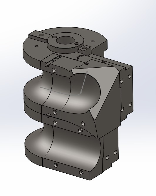
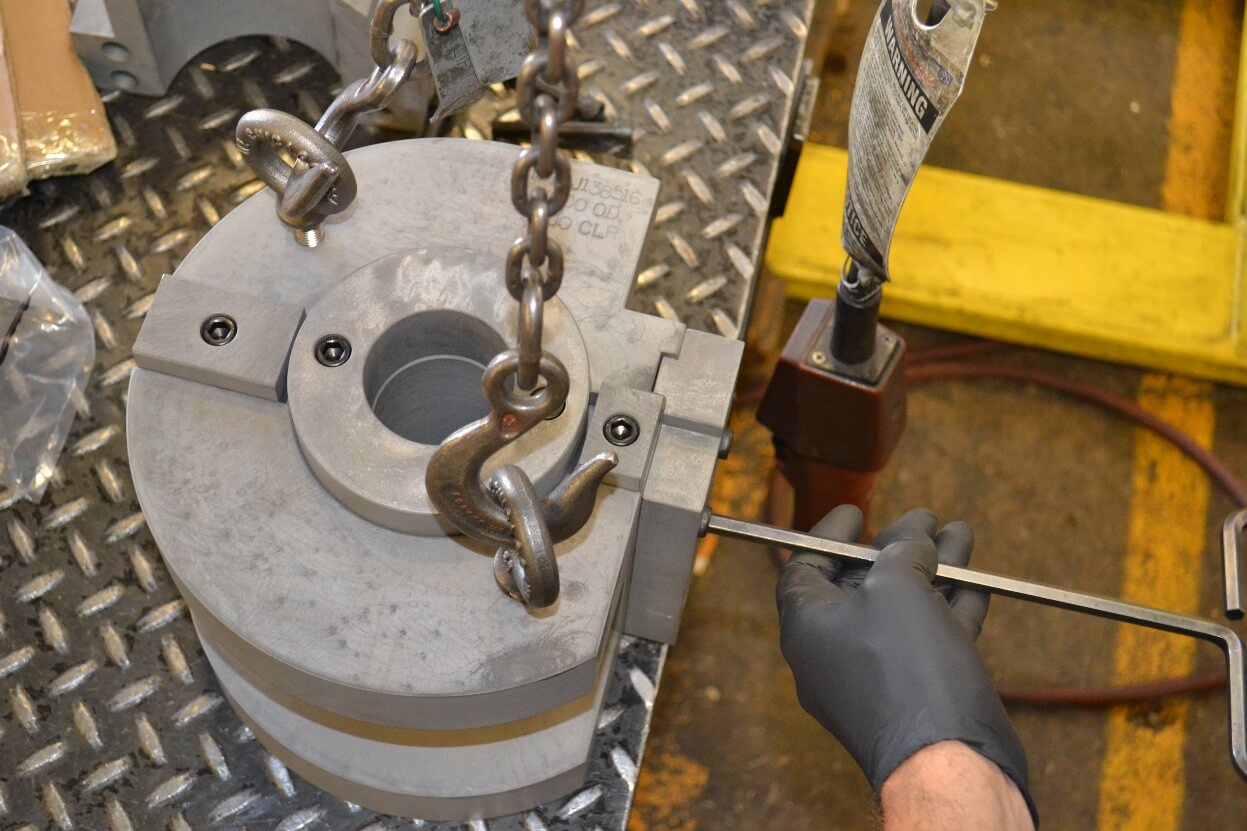
Tripple stack set up with showing mock up of collet position
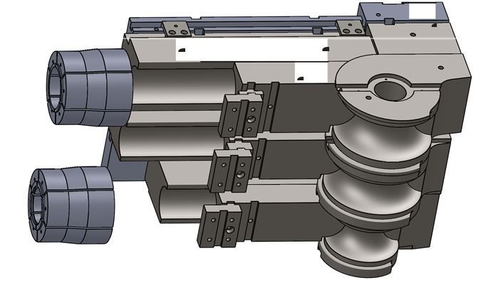
In the final design version, the pressure die will be shortened and the wiper tip holders changed out for dogleg type. This allows for the final placement of the collet to tangent come within a few inches of the bend die tangent. Many other design considerations can come into the equation of a tooling system as opposed to die sets.
Some of these can include: – Quick change mandrel bodies precluding the need to thread them on and off the mandrel rod. – Quick change bend die inserts that use lock pins as opposed to machine screws. – Automatic lube features on wiper dies, tip holders and mandrels. – Adapter packages that allow the same die system to be used on multiple machines with different mounting designs.
While some considerations can be easily integrated into the process, others can bring in variables that don’t merit their complexity. The bottom line is always to drive the selection of the process, the equipment and the tooling system from the subject application. it is not only the first step its successful execution is the final goal.